Tapped-Transformer-MLI
Background
A novel tapped transformer topology for MLI is proposed and studied in detail. This topology consists of a transformer with multiple taps on the primary winding. These taps depend upon the number of voltage steps in staircase waveform. Switches are connected with the taps of the primary winding. By careful switching different taps are excited. The turns of the winding taps determine the size of the step produced on the secondary winding. For “m” number of steps “m-1” switches are used. Bidirectional switches are used in the proposed topology instead of a single switch. For realization of a bidirectional switch two MOSFETs are connected in series. It may appear that bidirectional switches increase the switch count and introduce complexity but they are triggered from a common gate signal and therefore the series combination of two switches can be considered as one bidirectional switch. Presented topology is tested in symmetric steps but can also be used to generate Asymmetric steps as well. Due to the optimized switching angle selection, THD is low in the output waveform. With the increase in the number of levels in proposed topology, THD further reduces. Hence it is more feasible to use this topology to deliver the required output voltage with minimum THDs. Furthermore, the transformer introduces electrical isolation which help in preventing un-necessary current circulations and the stresses on the switches are reduced. Hence the proposed topology has a lot of potential for its use in future. Proposed MLI topology is verified by simulations in MATLAB/Simulink.
Tapped-Transformer-MLI
In medium to high voltage systems, step up transformers will be used to step the voltage to 11kV. Hence, the transformer is indirectly a part of a grid connected inverter. a new topology is proposed that uses a single DC source and a transformer with multiple primary windings (or alternatively a tapped primary winding).
Proposed Topology
This topology consists of a transformer with multiple taps on the primary winding. These taps depend upon the number of voltage steps in staircase waveform. For “m” number of steps (m-1) switches are used. A 9 level is shown in Figure 1.1.
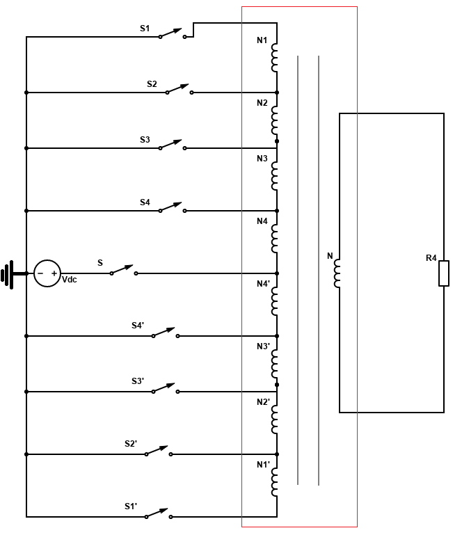
Figure 1.1 Schematic of a single phase 9-level tapped transformer MLI
From Figure 1.1, it is clear that, the topology uses a single DC source with a transformer. Therefore, issues related to the huge number of isolated power supplies, galvanic isolation and leakage current are eliminated. Switches are connected with the taps of the primary winding. By careful switching different taps are excited. The turns of the winding taps determine the size of the step produced on the secondary winding. Which means the symmetrical as well as asymmetrical steps can be generated. For 9 level staircase like waveform, eight taps are used on the primary side. The switching pattern along with desired output is shown in Figure 1.2.

Figure 1.2 Switching patterns for 9-level inverter design
Figure 1.2 shows the switching pattern of eight switches to obtain the desired waveform. Switches S1, S2, S3, and S4 control the positive half cycle, while the switches S1’, S2’, S3’, S4’ control the negative half cycle. The switches are ideal which means they will conduct only when the gate signal is applied. To obtain the 0 level switches S1 and S1‟ are simultaneously turned on. First step is obtained by closing the switch S1 while the other switches remain open. A current would flow through the taps with turns N1, N2, N3, N4 and the switch S1 to ground shown in Figure 1.3.
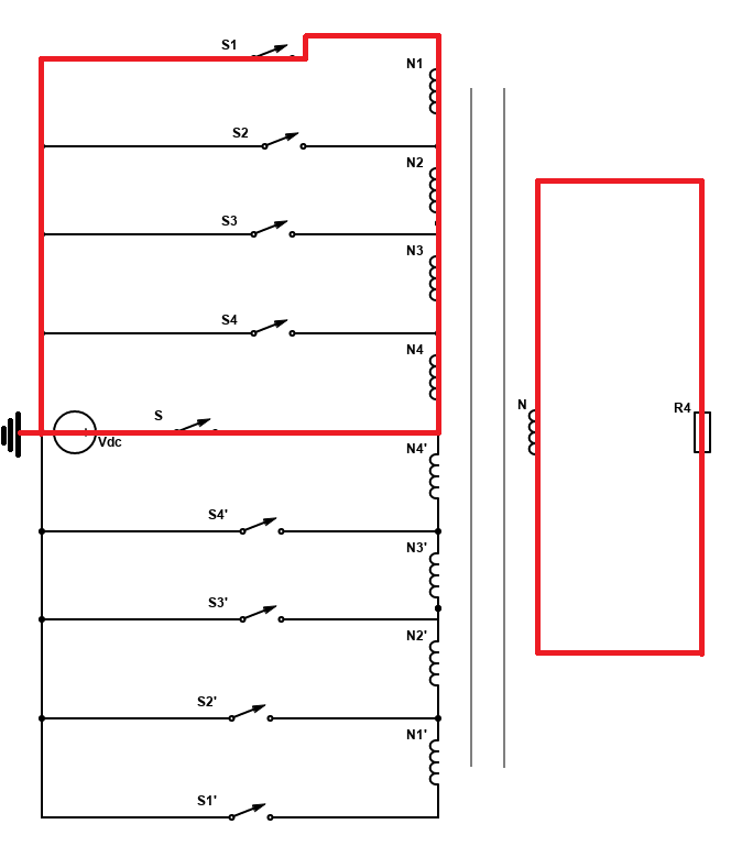
Figure 1.3 Generation of Voltage
This would produce a step corresponding to the voltage of . Similarly, to produce the second step S2 is closed while the rest of the switches are opened. A current would flow through taps with turns N2, N3, and N4 and switch S2 to ground shown in Figure 1.4. This would produce a step co-responding the voltage level.
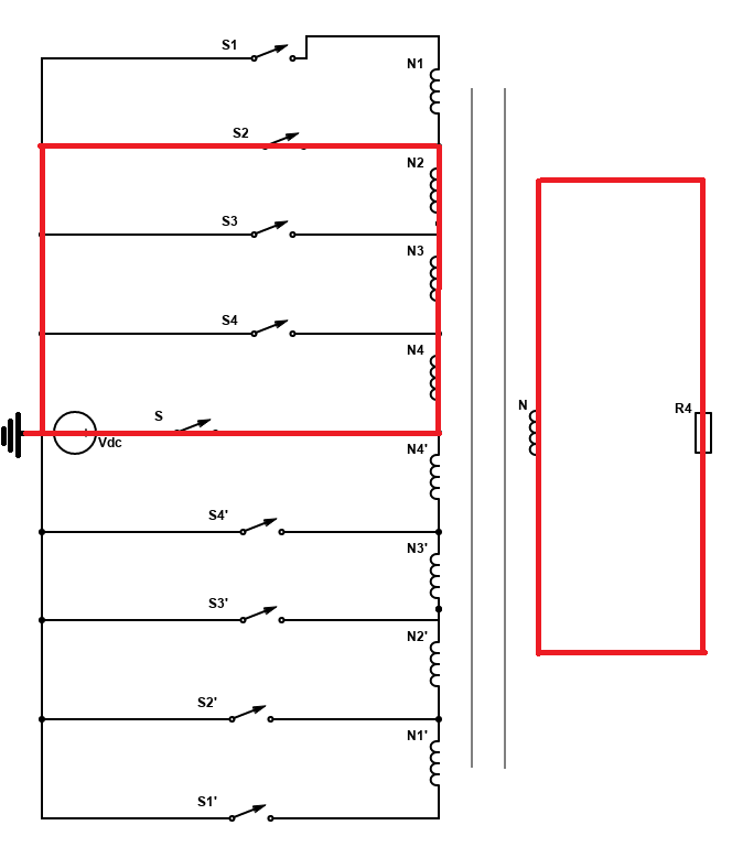
Figure 1.4 Generation of Voltage
The third and the fourth level is generated by closing the switch S3 and S4 respectively to obtain voltages corresponding to the levels of and shown in Figure 1.5 and 1.6.
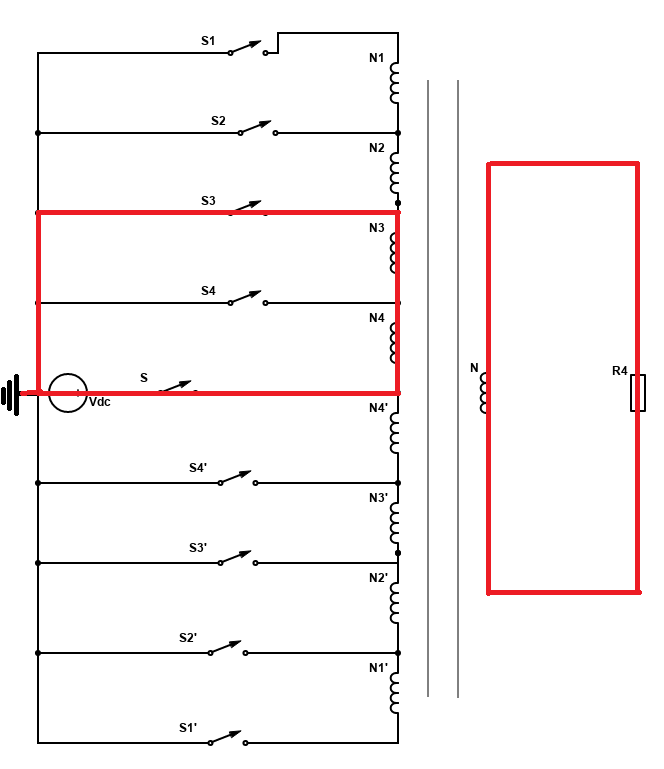
Figure 1.5 Generation of Voltage
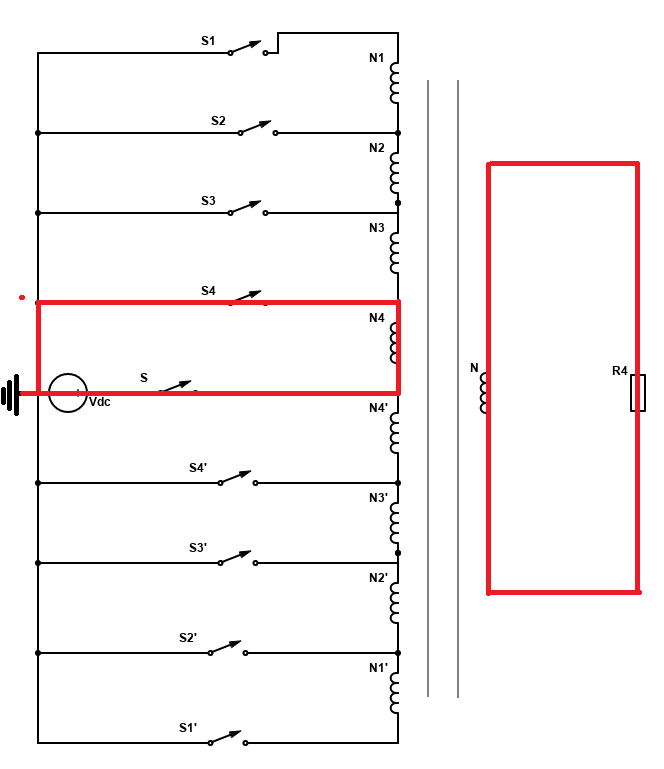
Figure 1.6 Generation of Voltage
Similarly, switches S1’, S2’, S3’ and S4’ are controlled to obtain the negative half cycle. From Figure 1.2 the switches S1and S1’ are operated three times in a cycle, S2, S3, S2’ and S3’ are operated twice in a cycle. Switches S4 and S4’ are operated once in a cycle.
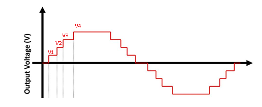
Figure 1.7 Four Voltage levels in output
The switching pattern is very simple as compared to the conventional MLIs. Hence a simple PWM based algorithm can be used to control the switching for minimum THD. Similarly, for a 9-level staircase waveform requires 8 switches while a typical CMLI used 12 switches. Apart from the large number of switches CMLI would also require two extra isolated DC power supply. Taking all these points into consideration it is obvious that the proposed MLI has all the advantages of CMLI with simple design and fewer components.
MATLAB/Simulink Simulations
To model the tapped transformer in MATLAB/Simulink, electromagnetic converters are coupled together to design primary side of tapped transformer. Electromagnetic converters convert the current flowing through the coil into magnetic flux according to Faraday’s law of electromagnetism .Bidirectional switches are used to give path to any current flowing in reverse. Bidirectional switches are designed by combining two MOSFETs.
Single phase design of the proposed 9-level inverter
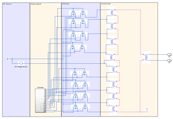
Figure 1.8 Circuit simulation of single phase 9-level MLI in Simulink
A. Gating signal for MOSFET’s
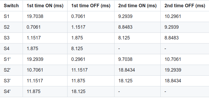
Gating signals for MOSFET’s are generated according to the optimum switching angles. Optimum switching angles are following,
α1 = 5.33°, α2 = 12.71°, α3 = 20.73°, α4 = 33.75°
Vgs for MOSFET’s
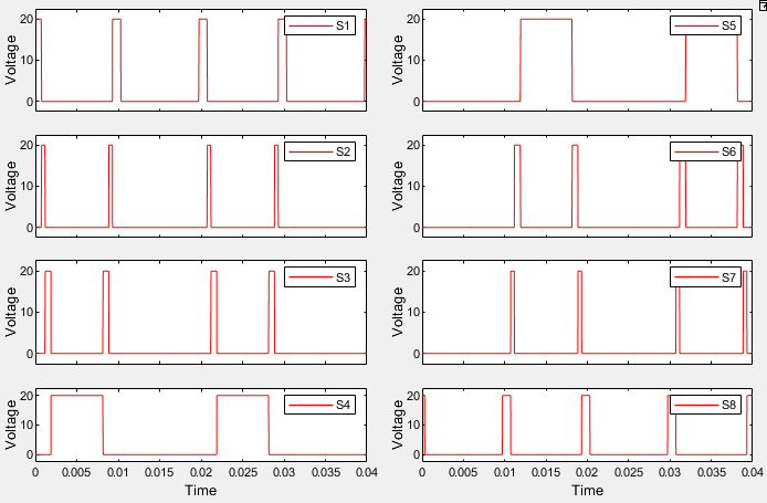
Figure 1.9 for MOSFET’s of single-phase 9-level inverter
Output voltage waveform
The gating signals shown in Figure 1.9 are applied to the MOSFET’s and we get the 9- level voltage waveform at the output shown in Figure 1.10.
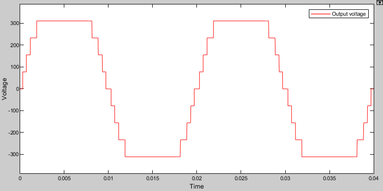
Figure 1.10 Output voltage waveform of single-phase 9-level inverter
Output voltage waveform is composed of four symmetric voltage levels. First level is 77.75 V, second level is 155.5 V, third level is 233.25 V and forth level is 311 V.
Three Phase Design of the proposed 9-level inverter
For three phase implementation of the proposed inverter topology, three single phase tapped transformers are designed and connected in wye configuration. Switching pattern is shifted by 120 degrees for phase B and 240 degrees for phase C. Also, three separate DC supplies are required for three phase implementation of the proposed topology. Circuit simulation of three phase design is shown in Figure 1.11 and output of three phase design is shown in 1.12.
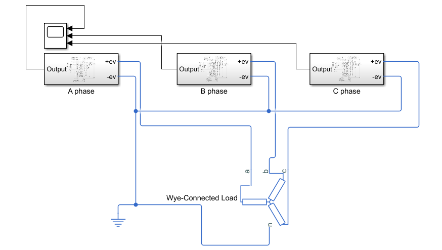
Figure 1.11 Circuit simulation of three phase design of the proposed topology
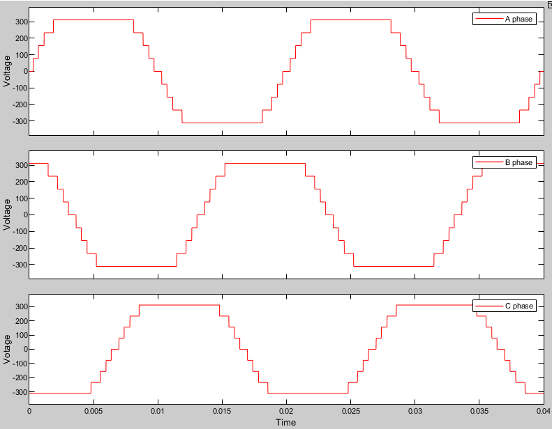
Figure 1.12 Output voltage waveform of three-phase 9-level inverter
Output waveform shows three phases A, B and C are shifted by 120 degrees and each phase is composed of 9-levels.
THD of 9 -level Inverter
The total harmonic distortion (THD) is a measurement of the harmonic distortion present in a signal and is defined as the ratio of the sum of the powers of all harmonic components to the power of the fundamental frequency. It represents the quality of the signal. Frequency analysis of 9-level inverter is also performed in MATLAB/Simulink. THD for 9-level inverter is 3.95%.

Figure 1.13 Line to line voltage of three-phase 9-level inverter
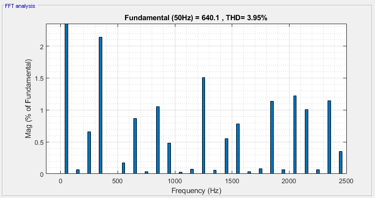
Figure 1.14 THD of 9-level inverter